
read the article

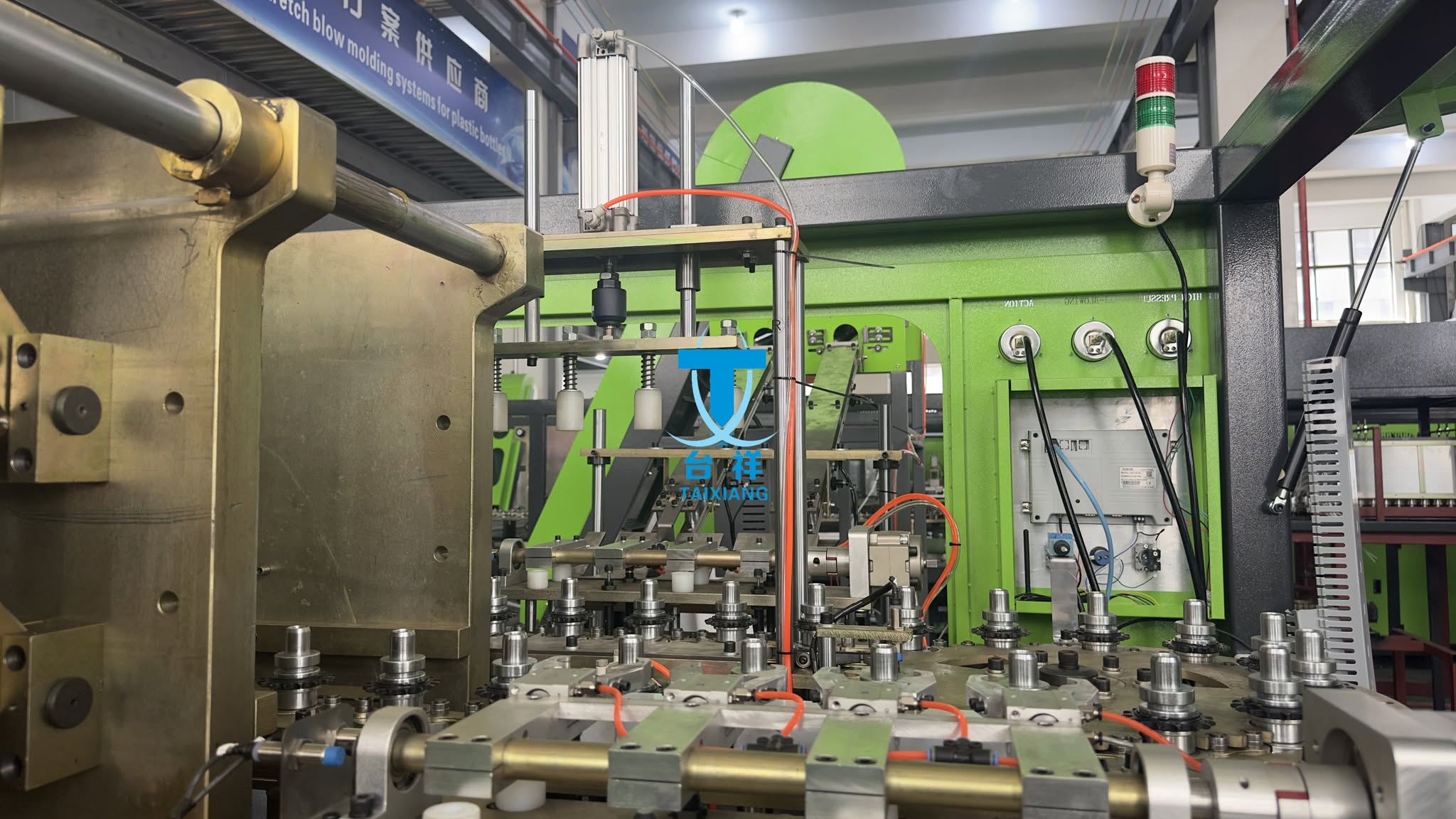
Introduction: Why Pre-Delivery Preparation Determines Your ROI
Most PET bottle manufacturers focus on the machine specification sheet. They compare cavities, output rates, and energy consumption. But the single factor that most reliably determines whether a new blow molding machine reaches rated capacity within the first month is not the machine itself—it is the site readiness before the container arrives.
At TAIXIANG MACHINE, we have commissioned hundreds of semi-automatic and fully automatic PET blowing systems across more than 80 countries. The pattern is consistent: factories that complete the pre-delivery checklist below achieve stable production within 3–5 days of rigging. Factories that wait until the machine is on the floor to address utilities, air quality, or floor leveling routinely lose 2–3 weeks to rework and troubleshooting.
This guide is not a generic installation manual. It is the exact preparation protocol we walk our clients through during the pre-shipment phase, calibrated to the operational realities of PET stretch blow molding—from high-pressure air purity to chiller sizing to the often-overlooked question of floor load distribution.
1. Facility and Foundation: The Load-Bearing Reality
1.1 Floor Load and Leveling Tolerance
A PET blow molding machine is not a static load. The clamping unit generates significant dynamic force during each cycle, and the machine's center of gravity shifts as the carriage and mold move. For TAIXIANG's semi-automatic series (models covering 3L to 5-gallon capacities), the machine weight ranges from 550 kg for a single-cavity 3L unit to 1,500 kg for a 5-gallon configuration with 25T clamping force. Fully automatic models with 4–9 cavities are substantially heavier and require a reinforced concrete slab rated for continuous vibration absorption.
The preparation action: Verify that your floor slab meets the following minimums before delivery:
| Machine Class | Typical Weight Range | Minimum Slab Thickness | Leveling Tolerance |
|---|---|---|---|
| Semi-auto 1–2 cavity | 550–800 kg | 150 mm reinforced | ≤ 1 mm/m |
| Semi-auto 4 cavity | 800–1,000 kg | 200 mm reinforced | ≤ 1 mm/m |
| Fully auto 4–6 cavity | 2,500–4,500 kg | 250 mm reinforced | ≤ 0.5 mm/m |
| Fully auto 8–9 cavity | 5,000–8,000 kg | 300 mm reinforced | ≤ 0.5 mm/m |
Leveling is not optional. A machine out of level by 2 mm across its length will exhibit uneven clamping pressure, accelerated mold wear, and inconsistent wall thickness on the non-drive side. Use a precision machinist's level, not a carpenter's level, and document the readings before signing the rigging receipt.
1.2 Clearance and Service Access
The machine footprint on the specification sheet is the static dimension. The operational footprint is larger. Plan for:
- Front access: Minimum 1.5 m for mold changes and preform loading (semi-auto) or conveyor access (fully auto).
- Rear access: Minimum 1.0 m for electrical panel and pneumatic maintenance.
- Side clearance: 0.8 m on at least one side for heater oven access and lamp replacement.
- Overhead: For fully automatic models with top-mounted preform feeders, verify ceiling height accommodates the feeder in its raised position plus 300 mm clearance.
A common mistake in leased industrial spaces: the machine fits through the door but the preform hopper or oven hood does not clear the ceiling sprinkler line. Measure the tallest component, not the base machine.
2. High-Pressure Air: The Most Underestimated Utility
2.1 Pressure and Volume Requirements
PET stretch blow molding requires two distinct air circuits, and conflating them is a frequent source of commissioning delays.
High-pressure (HP) air performs the actual bottle formation. For standard PET water and CSD bottles, the blowing pressure typically falls between 25–35 bar (2.5–3.5 MPa), with 30 bar being the practical working setpoint for most 500ml–2L applications. TAIXIANG's semi-automatic machines operate at a maximum blowing pressure of approximately 3.0 MPa, with consumption varying by cavity count and cycle time.
Low-pressure (LP) air drives the pneumatic actuators, valves, and safety interlocks. This circuit requires 6–8 bar (0.6–0.8 MPa) and must be dry and oil-free.
| Machine Configuration | HP Air Consumption (approx.) | HP Receiver Tank | LP Air Consumption |
|---|---|---|---|
| Semi-auto 1 cavity | 0.3–0.5 Nm³/min | 300–500 L | 0.1–0.2 Nm³/min |
| Semi-auto 2 cavity | 0.6–0.9 Nm³/min | 500–800 L | 0.2–0.3 Nm³/min |
| Fully auto 4 cavity | 1.2–1.8 Nm³/min | 1,000–1,500 L | 0.4–0.6 Nm³/min |
| Fully auto 6–9 cavity | 2.5–4.0 Nm³/min | 2,000–3,000 L | 0.8–1.2 Nm³/min |
2.2 Air Quality: Where Bottles Fail
Moisture and oil contamination in the HP circuit do not merely damage valves. They cause visible defects: pearlescent haze on bottle walls, inconsistent stretch ratios, and in severe cases, stress cracking at the base. The air dryer is not a peripheral accessory; it is a quality-critical component.
Pre-delivery action: Confirm that your compressed air system includes:
- Refrigerated dryer sized for the HP compressor's full output, with a pressure dew point of ≤ 3°C.
- Coalescing filters (0.01 micron) on the HP line downstream of the dryer.
- Activated carbon filter if the compressor is oil-lubricated. For oil-free compressors, carbon filtration is optional but recommended for food-grade applications.
- Air receiver tank sized at minimum 1/3 of the compressor's per-minute output to buffer pressure spikes during blow cycles.
Expert tip: If your factory air is shared with other equipment, install a dedicated HP receiver and regulator at the blow molding machine. Pressure fluctuation from a nearby filling line will manifest as inconsistent bottle weight and wall distribution.
3. Cooling Water: Chiller Sizing and Circuit Separation
3.1 Two Circuits, Two Temperatures
PET blow molding uses cooling water in two distinct loops with different temperature requirements:
Mold cooling circuit: 8–14°C. This is the primary heat removal path for the blown bottle. Insufficient mold cooling causes sticking, deformation on ejection, and extended cycle times.
Lamp/oven cooling circuit (if equipped): 12–24°C. Some heater oven designs use water-cooled reflectors or lamp housings to extend IR lamp life and maintain consistent heating profiles.
These circuits should not be combined. Mixing them forces the chiller to operate at the lower setpoint, wasting energy and potentially causing condensation on the oven components.
3.2 Chiller Sizing Quick Reference
| Machine Class | Mold Cooling Load | Recommended Chiller |
|---|---|---|
| Semi-auto 1 cavity (3L–5L) | 2–3 kW | 3–5 HP (2.5–3.5 TR) |
| Semi-auto 2–4 cavity | 4–8 kW | 5–10 HP |
| Fully auto 4 cavity | 8–12 kW | 10–15 HP |
| Fully auto 6–9 cavity | 15–25 kW | 15–30 HP |
These figures assume a 10°C mold temperature setpoint and a 25–30°C ambient. If your factory ambient exceeds 35°C, upsize the chiller by 20–30%.
Pre-delivery action: Confirm cooling water piping is installed and pressure-tested before the machine arrives. The connection points on TAIXIANG machines use standard BSP or NPT threads; verify the matching adapters are on hand. A missing 1-inch fitting can delay commissioning by a full day.
4. Electrical Supply and Safety Grounding
4.1 Voltage Stability and Phase Balance
PET blow molding machines are sensitive to voltage fluctuation because the IR heater lamps and servo-driven clamp (on automatic models) operate on precise power profiles. A voltage sag of 10% during the heating phase extends preform conditioning time and produces inconsistent parison temperatures.
Requirements:
- Voltage tolerance: ±10% of rated nameplate voltage (typically 380V/3-phase/50Hz or 440V/3-phase/60Hz depending on destination market).
- Ground resistance: ≤ 4Ω. This is a safety requirement, not a suggestion. Verify with a ground resistance tester before the machine is connected.
- Phase balance: If the factory has large single-phase loads (welding equipment, large ovens), verify phase balance at the machine disconnect. Unbalanced phases cause heater zone temperature deviations and reduce lamp life.
4.2 What to Have Ready at the Disconnect
| Item | Specification |
|---|---|
| Main breaker | Sized to machine FLA × 1.25 |
| Cable | Copper, sized per local code for the machine's rated current |
| Ground conductor | Separate grounding conductor, not neutral |
| Surge protection | Recommended for regions with unstable grid |
Do not plan to "temporarily" power the machine from an extension board. Heater warm-up alone can draw 60–80% of the machine's rated load for the first 3–5 minutes of each shift.
5. Mold and Preform Readiness: The Overlooked Variable
5.1 Mold Inspection Before Installation
Every mold should be inspected and prepared before it touches the machine. This is especially critical for molds that have been in storage or were shipped separately from the machine.
Checklist:
- Cavity surface: No scratches, rust spots, or residual plastic from test shots. A 0.05 mm scratch on the cavity wall becomes a visible defect on every bottle.
- Cooling channels: Flow-test each circuit. A partially blocked mold cooling channel will cause localized hot spots and dimensional inconsistency.
- Blow pin and seal: Verify the blow pin O-rings are supple and correctly sized. A hardened O-ring leaks HP air and produces underblown bottles.
- Vent slots: Clean with a soft brass brush. Clogged vents trap air between the parison and cavity, causing surface defects.
5.2 Preform Specification and Storage
The preform is half the process. Before the machine arrives, confirm:
- Preform IV (intrinsic viscosity): Match to bottle application. Water bottles typically use 0.78–0.80 IV; CSD requires 0.80–0.84 for pressure resistance.
- Moisture content: ≤ 50 ppm. Preforms that have absorbed ambient moisture turn hazy and weak during blowing. If your storage area is humid, plan for a dehumidifying dryer before the preforms enter the oven.
- Dimensional consistency: Measure wall thickness at the body and neck finish diameter on a sample of 20 preforms. Variation beyond ±0.05 mm will cause uneven heating and require per-preform oven adjustment—a costly manual intervention on semi-automatic machines.
Storage preparation: Install shelving or racking that keeps preforms off the floor and away from direct sunlight. PET preforms exposed to UV degrade at the surface, which manifests as surface defects after blowing. Keep sealed in the original liner bags until loading into the hopper.
6. Documentation and Personnel: What TAIXIANG Provides and What You Must Assign
6.1 The Pre-Delivery Document Package
TAIXIANG ships each machine with a documentation set that includes:
- Electrical schematic (as-built, not generic)
- Pneumatic circuit diagram
- Hydraulic schematic (if applicable)
- Preventive maintenance schedule with lubrication points and intervals
- Spare parts list with part numbers and recommended stock quantities
- Troubleshooting guide indexed by symptom
Action item: Assign one person to receive this package, log it, and file it in a location accessible to maintenance—not in the purchasing department's filing cabinet. We have seen machines run without proper lubrication for months because the manual was never unpacked.
6.2 Personnel Assignment
For a semi-automatic machine, a single operator can achieve rated output after approximately one day of training, given the one-button operation design of TAIXIANG's semi-auto series. However, pre-delivery preparation should identify:
- Primary operator: Who will run the machine daily.
- Maintenance technician: Who will perform weekly lubrication, monthly filter changes, and quarterly belt tension checks.
- Electrical competent person: Who can safely open the control panel for diagnostics.
Name these individuals before the machine arrives. Commissioning engineers can train operators, but they cannot compensate for a factory that has not assigned responsibility for daily upkeep.
7. The Pre-Delivery Checklist (Condensed)
Use this as a sign-off document. Every box should be checked before the container is booked.
| Category | Item | Verified By | Date |
|---|---|---|---|
| Floor | Slab thickness meets machine class minimum | ||
| Leveling tolerance ≤ 1 mm/m confirmed | |||
| Service clearances marked on floor | |||
| Air | HP compressor rated for ≥ 30 bar | ||
| Refrigerated dryer installed and operational | |||
| Coalescing filter on HP line | |||
| Receiver tank sized per Section 2.1 | |||
| Water | Chiller sized per Section 3.2 | ||
| Mold circuit piped and leak-tested | |||
| Oven circuit separated (if applicable) | |||
| Electrical | Voltage stable within ±10% | ||
| Ground resistance ≤ 4Ω measured | |||
| Main breaker and cable sized correctly | |||
| Mold | Cavity surfaces inspected and clean | ||
| Cooling channels flow-tested | |||
| Blow pin O-rings replaced if aged | |||
| Preform | IV and moisture spec confirmed with supplier | ||
| Storage racking installed, UV-protected | |||
| Personnel | Operator, maintenance, and electrical roles assigned | ||
| Documentation filing location designated |
Why TAIXIANG Approaches Installation as a Partnership, Not a Handoff
The checklist above is not generic advice. It reflects the specific preparation patterns we have observed across our semi-automatic and fully automatic PET blow molding installations—from 1-cavity 3L units in small water plants to 9-cavity high-speed lines producing over 12,000 bottles per hour. Our machines are designed for accessible maintenance and straightforward installation, but no machine can overcome a site that is not ready for it.
When you purchase a TAIXIANG system, you receive more than the machine. You receive a pre-shipment consultation that walks through this preparation list, documentation written for the maintenance technician who will actually use it, and commissioning support from engineers who have seen the failure modes that arise when foundations are out of level or air is wet. We are not a company that ships boxes and disappears. We are a PET blow molding solutions partner, and that partnership begins before the machine leaves our floor.